ALU Card¶
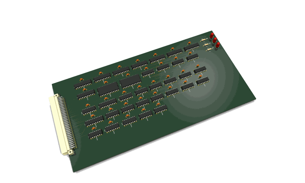
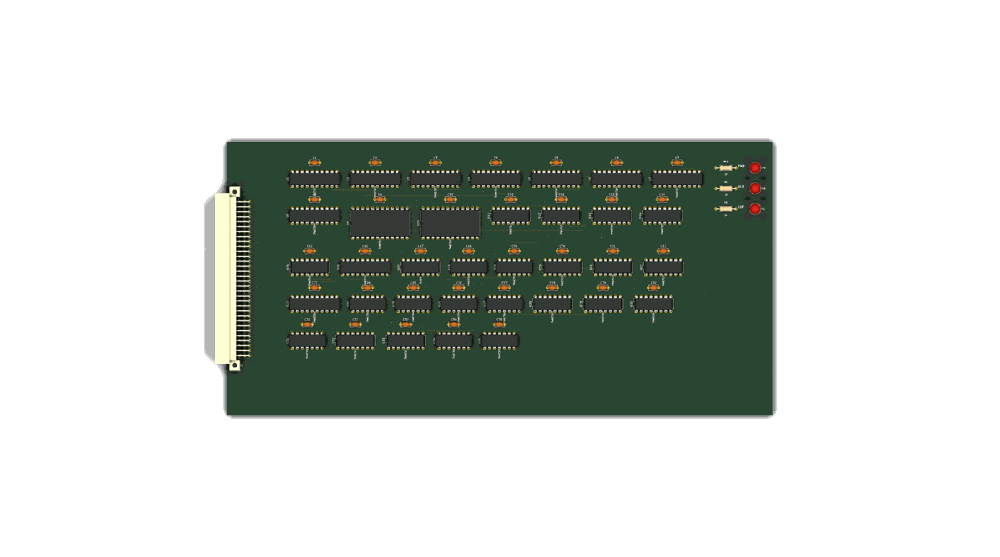
The board as routed in KiCad (3D render; top view).
Theory of operation: p8x-alu-card-theory.md — deep walkthrough of inputs/outputs, signal flow, and logic.
Holds the two ALU operand registers (A, B), the two hidden microcode temporaries (T, T2), the 74181-based ALU with a post-ALU shifter, and the FLAGS register. All arithmetic and logic happens here.
This README describes the circuit as actually built in
generators/gen_eagle.py. See p8x-system-design.md §5 for the overview and p8x-bus-definition.md for bus pins.
Chip inventory¶
| Ref | Device | Role |
|---|---|---|
| U1, U2 | 74377 + 74244 | A register (load latch + bus-drive buffer) |
| U3, U4 | 74377 + 74244 | B register |
| U5, U6 | 74377 + 74244 | T register (hidden temp) |
| U7, U8 | 74377 + 74244 | T2 register (hidden temp) |
| U9, U10 | 74181 | ALU, low and high nibble |
| U11 | 74182 | Carry-lookahead generator across the two 74181s |
| U12–U15 | 74157 | Two-stage shifter (pass / <<1 / >>1) |
| U16 | 74244 | ALU-result bus driver |
| U17 | 74175 | FLAGS register (C, Z, N, V) |
| U18 | 74260 | Zero-detect NOR over the result |
| U19 | 74HCT08 | AND glue (zero combine, flag-clock gate) |
| U20 | 74138 | DOE decoder (codes 1–6) |
| U21 | 74138 | DLD decoder (codes 1–5) |
| U22 | 74157 | Flag mux — select computed flags vs restore-from-bus |
| U23 | 74244 | FLAGS → data bus driver |
| U24, U25 | 74HCT32 / 74HCT00 | Flag-load and restore gating |
How it works¶
The four registers¶
A, B, T, T2 are each a 74377 (8-bit latch with a load enable) paired with a
74244 output buffer. The 74377 loads from the data bus when its DLD code is
decoded by U21 (-LDA/-LDB/-LDT/-LDT2). The 74244 drives the register's value
back onto the data bus when its DOE code is decoded by U20. A and B also feed the
74181 inputs directly and continuously — they don't need to be on the bus for the
ALU to operate on them.
The ALU (74181 + 74182)¶
Two 74181s (U9 low nibble, U10 high nibble) form the 8-bit ALU. Function is set by
the backplane lines ALUS0–3 (operation select), ALUM (logic vs arithmetic),
and CIN (carry in). Instead of rippling carry between the two 74181s, the
74182 carry-lookahead generator (U11) takes their propagate/generate outputs
(!P/!G) and produces the fast intermediate carry CNX into the high nibble —
keeping the carry chain short and fast.
Carry flag polarity quirk: the C flag latches the raw 74181
Cn+4pin, which is active-low (C=1 means no carry out). This is deliberate and the emulator reproduces it faithfully — do not "fix" it. See p8x-bus-definition.md §3.8.
The shifter¶
Two stages of 74157 muxes (U12/U13 then U14/U15) sit after the ALU, selected by SH0/SH1, giving pass-through, shift-left, or shift-right. The shift-in bit is wired to CIN. The shifted result is driven onto the data bus by U16 (74244) when DOE selects the ALU result (code 5).
Flags¶
- Z (zero): U18 (74260) NORs the result bits, combined in U19 — asserted when the whole 8-bit result is zero.
- N (negative): bit 7 of the result.
- C (carry): the raw 74181
Cn+4(see quirk above). - V (overflow): hardwired 0 in rev A — unimplemented (see BACKLOG).
The 74175 (U17) latches all four flags, but only when LDF is asserted (the flag clock is gated by U19/U24 so non-ALU cycles don't disturb the flags). The U22 74157 mux lets FLAGS be either freshly computed or restored from the data bus (DLD code 5, for PLP-style flag pops), and U23 (74244) drives FLAGS onto the bus for PHP-style pushes (DOE code 6).
Bus codes this card owns¶
- DOE: 1=A, 2=B, 3=T, 4=T2, 5=ALU result, 6=FLAGS
- DLD: 1=A, 2=B, 3=T, 4=T2, 5=FLAGS (restore)
LEDs¶
PWR (green), ALU (green — result on bus), LDF (yellow — flags latching).